Safe Lock
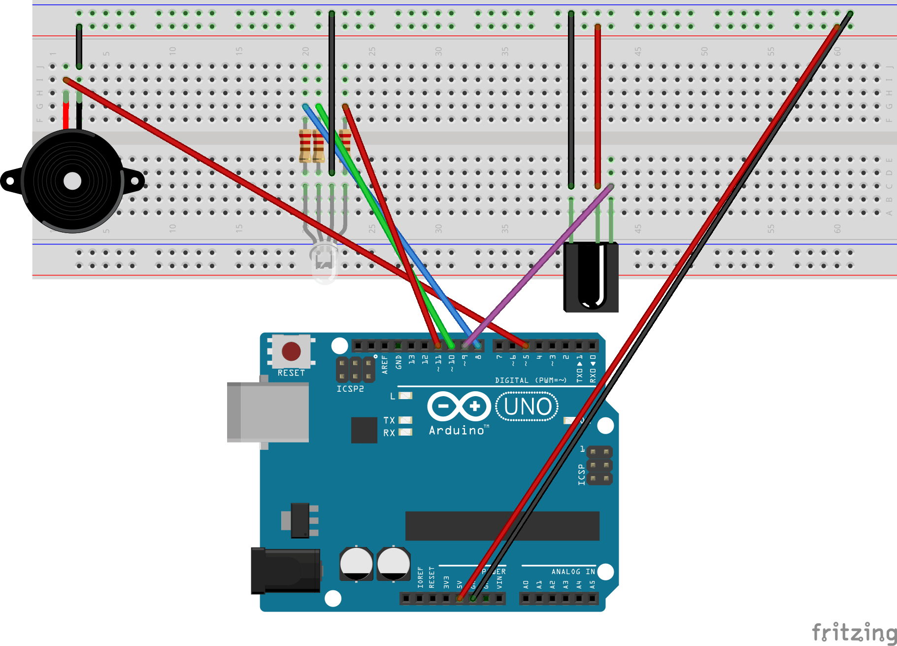
This projects functions as a digital locking mechanism for a safe, using an IR (infrared) Receiver to decode signals transmitted by a remote. The system requires the user to input a 3-digit combination via the remote. For each correct digit entered, a blue LED illuminates for feedback. After the successful entry of the full combination, a green LED is activated, and a high-frequency tone is emitted by the passive buzzer. If the combination is incorrect, a low-frequency tone is played. The code and diagram are below.
#include "pitches.h"
#include <IRremote.h>
const int IRpin = 9; // Pin for the IR receiver module
IRrecv IR(IRpin);
decode_results cmd;

int note[] = {NOTE_C3, NOTE_A5}; // Stores the notes

// Values for the code of the safe lock using the remote
int firstValue = 0;
int secondValue = 0;
int thirdValue = 0;
int cmdval; // Value to clear

// RGB LED pins
const int redPin = 11;
const int greenPin = 10;
const int bluePin = 8;

// Buzzer pin
const int buzzerPin = 5;
This project utilizes two external libraries and several global variables to manage functionality.
The first #include imports a header file containing predefined
pitch constants for sound generation, while the second imports the IRremote.h library,
which enables communication with the IR receiver module. Key variables include the digital pin assigned to the IR receiver,
an instance of the IRrecv class, and a decode_results
object for parsing incoming IR signals from the remote. Additional variables define tone frequencies for the passive buzzer,
and placeholders to store user input values corresponding to remote key presses. Further pin assignments are
declared to control various hardware components, such as LEDs and the buzzer.
void turnGreen() {
    analogWrite(redPin, 0);
    analogWrite(greenPin, 255);
    analogWrite(bluePin, 0);
    delay(1000);
}

void turnBlue() {
    analogWrite(redPin, 0);
    analogWrite(greenPin, 0);
    analogWrite(bluePin, 255);
    delay(500);
}

// Sets LED color back to red since everything has been reset
void clearProgram() {
    delay(500);
    Serial.println("Cleared");
    Serial.println();
    firstValue = 0;
    secondValue = 0;
    thirdValue = 0;
    cmdval = 0;
    turnRed();
}
The utility methods above are implemented to improve code readability and modularity. Each method is
relatively self-explanatory; however, some details may need further clarification. Specifically,
analogWrite() is called three times in
turnBlue() (as well as the other color-based functions) because
the LED in use is an RGB LED, which required independent control for the red, green, and blue channels.
This type of LED has four pins, and it is able to display a large range of color values. Additionally,
while the turnRed() function is not included here, its structure
mirrors that of the turnBlue() method.
if ((firstValue != 0) && (secondValue != 0) &&
    (thirdValue != 0))
{
    // Checks if the code is 2-3-4
    if ((firstValue == 6375) && (secondValue == 31365) &&
        (thirdValue == 4335))
    {
        // Change color of LED to green
        Serial.println("Combination unlocked");
        tone(buzzerPin, note[1], 500);
        turnGreen();
    } else
        tone(buzzerPin, note[0], 500);

    clearProgram();
}
The program contains numerous conditional statements, but this one is particularly important.
The outer if checks whether all three input values have
been initialized. Another if nested within verifies if
the inputs match a specific combination. I identified these expected values by monitoring values
from the IR remote in the Serial monitor. However, they were inconsistent, so I selected the
most frequent values. If the combination is correct, the LED turns green and a high-frequency
tone plays; otherwise, a low tone is emitted. The system then resets using the
clearProgram() method.